Spinner: Difference between revisions
Wigsplitta (talk | contribs) No edit summary |
Wigsplitta (talk | contribs) |
||
| (62 intermediate revisions by the same user not shown) | |||
| Line 1: | Line 1: | ||
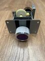
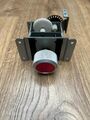
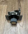
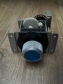
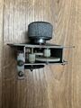
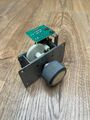
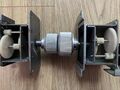
A '''Spinner''' is a type of control interface used in several arcade titles. To install a spinner, depending on the type, you either need to remove the knob and install it like a joystick, or completely disassemble the spinner and remove the c-ring to release the shaft, and then re-build the spinner around the control panel. When installing the spinner, make sure the encoder wheel doesn't touch the optical switches when in upright position, as this will cause resistance on the wheel and make the spinner difficult to use. | A '''Spinner''' is a type of control interface used in several arcade titles. To install a spinner, depending on the type, you either need to remove the knob and install it like a joystick (Capcom/Seimitsu), or completely disassemble the spinner (Taito) and remove the c-ring to release the shaft, and then re-build the spinner around the control panel.<br> | ||
When installing the spinner, make sure the encoder wheel doesn't touch the optical switches when in upright position, as this will cause resistance on the wheel and make the spinner difficult to use.<br> | |||
More recent spinners utilise the standard 30mm button hole (Ultimarc/Axunworks<ref>[https://www.axunworks.com/product-p669531.html Axunworks]</ref>) as a way of mounting onto the control panel. | |||
== Gallery == | == Gallery == | ||
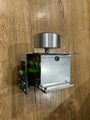
'''Seimitsu''' | |||
<gallery> | |||
Image:Seimitsu_Spinner1.jpg | |||
</gallery> | |||
'''Taito''' | |||
<gallery> | |||
Image:Taito_Spinner_1.jpg|Purple 4 gear flat plate | |||
Image:Taito_Spinner_2.jpg|Red 4 gear 'S' plate | |||
Image:Taito_Spinner_13.jpg|Gold 4 gear low profile flat plate | |||
Image:Taito_Spinner_14.jpg|Blue 4 gear 'S' plate | |||
</gallery> | |||
<gallery> | <gallery> | ||
Image:Taito_Spinner_3.jpg | Image:Taito_Spinner_3.jpg | ||
Image:Taito_Spinner_4.jpg | Image:Taito_Spinner_4.jpg | ||
Image:Taito_Spinner_6.jpg | |||
Image:Taito_Spinner_5.jpg | Image:Taito_Spinner_5.jpg | ||
Image: | </gallery> | ||
<gallery> | |||
Image:Taito_Spinner_8.jpg | |||
Image:Taito_Spinner_7.jpg | Image:Taito_Spinner_7.jpg | ||
Image: | </gallery> | ||
< | <gallery> | ||
Image:Opto_Board_1.jpg| | Image:Taito_Spinner_13.jpg|Shallow profile | ||
Image:Opto_Board_2.jpg| | Image:Taito_Spinner_9.jpg | ||
Image: | Image:Taito_Spinner_10.jpg | ||
Image: | Image:Taito_Spinner_11.jpg | ||
</gallery> | |||
Image: | <gallery> | ||
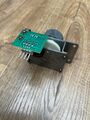
Image: | Image:Opto_Board_1.jpg|4 pin Opto pcb | ||
Image:Opto_Board_7.jpg|Repro | Image:Opto_Board_2.jpg|4 pin Opto pcb | ||
Image:Opto_Board_8.jpg|Repro | </gallery> | ||
< | <gallery> | ||
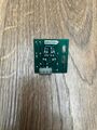
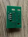
Image:Opto_Board_5.jpg|6 pin Opto pcb | |||
Image:Opto_Board_6.jpg|6 pin Opto pcb | |||
Image:Opto_Board_9.jpg|6 pin Opto pcb Alt | |||
Image:Opto_Board_10.jpg|6 pin Opto pcb Alt | |||
</gallery> | |||
<gallery> | |||
Image:Opto_Board_3.jpg|Wico Opto pcb | |||
Image:Opto_Board_4.jpg|Wico Opto pcb | |||
Image:Opto_Board_7.jpg|Repro Opto pcb | |||
Image:Opto_Board_8.jpg|Repro Opto pcb | |||
</gallery> | |||
<gallery> | |||
Image:Opto_Board_11.jpeg|Repro Opto pcb | |||
Image:Opto_Board_12.jpeg|Repro Opto pcb | |||
</gallery> | |||
<gallery> | |||
Image:Taito_Spinner_12.jpg|Shallow vs Deep profile | |||
Image:Taito_Spinner_15.jpeg|35mm vs 40mm knob | |||
Image:Taito_Spinner_CP.jpg | |||
</gallery> | |||
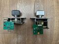
'''Capcom''' | |||
<gallery> | |||
Image:Capcom_Spinner_Repro1.jpg|TR Repro Spinner | |||
Image:Capcom_Spinner_Repro2.jpg|TR Repro Spinner | |||
Image:Capcom_Spinner_Repro3.jpg|TR Repro Spinner | |||
Image:Capcom_Spinner_Repro4.jpg|TR Repro Spinner | |||
</gallery> | |||
<gallery> | |||
Image:Capcom_Spinner_CP.jpg|TR Repro Spinner and CP setup | |||
</gallery> | |||
'''Ultimarc''' | |||
<gallery> | |||
Image:Ultimarc_Spinner_1.jpg | |||
Image:Ultimarc_Spinner_2.jpg | |||
Image:Ultimarc_Spinner_3.jpg | |||
Image:Ultimarc_Spinner_CP.jpg | |||
</gallery> | |||
'''Axunworks''' | |||
<gallery> | |||
Image:Axunworks_Spinner1.jpg | |||
</gallery> | </gallery> | ||
| Line 41: | Line 94: | ||
|- | |- | ||
| [[Cameltry]]|| Left and Right bind to L/R on the harness | | [[Cameltry]]|| Left and Right bind to L/R on the harness | ||
|- | |||
| [[Eco Fighters]]|| Connectors on official Capcom JAMMA adapter | |||
|- | |||
| [[Forgotten Worlds]]|| Onboard PCB connector | |||
|- | |- | ||
| [[Puzz Loop]]|| CN6 pinout 1. +5VDC 2. 1p 3. 2p 4. - 5. - 6. 1p 7. 2p 8. GND <ref>[http://forum.arcadeotaku.com/viewtopic.php?f=26&t=6984 Puzz Loop pinout]</ref> | | [[Puzz Loop]]|| CN6 pinout 1. +5VDC 2. 1p 3. 2p 4. - 5. - 6. 1p 7. 2p 8. GND <ref>[http://forum.arcadeotaku.com/viewtopic.php?f=26&t=6984 Puzz Loop pinout]</ref> | ||
| Line 48: | Line 105: | ||
|} | |} | ||
== Seimitsu LS-29 | * [https://docs.google.com/spreadsheets/d/1gSfIBCuo3xa7w6aFPNppbBAyCY7t1yNRw81gx5Dp9Jk/htmlview# External list of compatible games](includes alternative 2 way games such as Puzzle Bobble) | ||
Pin1: X1 | |||
== Pinouts == | |||
===Seimitsu LS-29=== | |||
Pin1: X1<br> | |||
Pin2: +5 Volts<br> | |||
Pin3: GND<br> | |||
Pin4: X2<ref>[http://www.neo-geo.com/forums/showthread.php?199615-Seimitsu-LS-29-connectors&p=2774116 Neo-Geo Forums]</ref><br> | |||
<hr> | |||
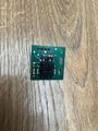
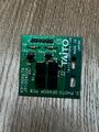
===Taito 4 Pin=== | |||
[[File:Taito_Spinner_4pin_Pinout.jpg|100px|thumb|right]] | |||
Pin1: Right<br> | |||
Pin2: +5 Volts<br> | |||
Pin3: GND<br> | |||
Pin4: Left<ref>[https://forums.arcade-museum.com/threads/taito-spinner-6-pin-wiring.494679 KLOV Arkanoid Manual]</ref><br> | |||
<hr> | |||
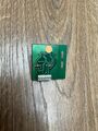
===Taito 6 Pin=== | |||
[[File:Taito_Spinner_6pin_Pinout.jpg|100px|thumb|right]] | |||
Pin1: +5 Volts<br> | |||
Pin2: +5 Volts<br> | |||
Pin3: GND<br> | |||
Pin4: GND<br> | |||
Pin5: Left<br> | |||
Pin6: Right<ref>[https://forums.arcade-museum.com/threads/taito-spinner-6-pin-wiring.494679 KLOV forums]</ref><br> | |||
<hr> | |||
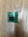
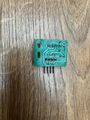
===Capcom=== | |||
[[File:Capcom_Spinner_Repro_Pinout.jpg|100px|thumb|right]] | |||
Pin1: B<br> | |||
Pin2: +5 Volts<br> | |||
Pin3: GND<br> | |||
Pin4: A<br> | |||
<hr> | |||
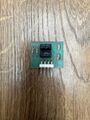
===Ultimarc to USB Interface=== | |||
[[File:Ultimarc_Spinner_USB.jpg|150px|thumb|right]] | |||
Pin1: +5 Volts (Brown)<br> | |||
Pin2: X2 (Green)<br> | |||
Pin3: GND (White)<br> | |||
Pin4: X1 (Yellow)<br> | |||
Pin5: Empty<ref>[https://www.ultimarc.com/trackballs-and-spinners/spinners/spintrak Ultimarc]</ref><br> | |||
<hr> | |||
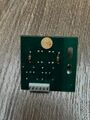
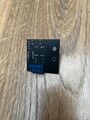
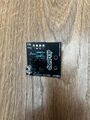
===MikesArcade repro=== | |||
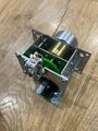
[[File:Opto_Board_13.png|150px|thumb|right]] | |||
Pin1: X1<br> | |||
Pin2: +5 Volts<br> | |||
Pin3: GND<br> | |||
Pin4: X2<ref>[https://mikesarcade.com/cgi-bin/store.pl?sku=ARKOPTO MikesArcade]</ref><br> | |||
<br> | |||
<br> | |||
<br> | |||
<br> | |||
== References == | == References == | ||
| Line 55: | Line 173: | ||
== External Links == | == External Links == | ||
* [http://www.zumbrovalley.net/readpost.php?artid=1 Everything you always wanted to know about optical arcade controls...] | * [http://www.zumbrovalley.net/readpost.php?artid=1 Everything you always wanted to know about optical arcade controls] | ||
* [https://mikesarcade.com/cgi-bin/store.pl?sku=ARKOPTO Replacement reproduction Opto PCBs] (Taito) | |||
* [https://www.arcadeshop.com/i/1704/2-3-encoder-wheel-atari-happ.htm Replacement reproduction encoder wheel] | |||
* [https://www.igus.com/iglide-ibh/flange-bearings/product-details/iglidur-g-m?artnr=GFM-0810-07 Replacement shaft sleeve] (Taito) | |||
[[Category:Controls]] | [[Category:Controls]] | ||
[[Category:Games]] | |||
[[Category:Technical]] | |||
Latest revision as of 16:31, 8 February 2026
A Spinner is a type of control interface used in several arcade titles. To install a spinner, depending on the type, you either need to remove the knob and install it like a joystick (Capcom/Seimitsu), or completely disassemble the spinner (Taito) and remove the c-ring to release the shaft, and then re-build the spinner around the control panel.
When installing the spinner, make sure the encoder wheel doesn't touch the optical switches when in upright position, as this will cause resistance on the wheel and make the spinner difficult to use.
More recent spinners utilise the standard 30mm button hole (Ultimarc/Axunworks[1]) as a way of mounting onto the control panel.
Gallery
Seimitsu

Taito
-
 Purple 4 gear flat plate
 -
 Red 4 gear 'S' plate
 -
 Gold 4 gear low profile flat plate
 -
 Blue 4 gear 'S' plate


-
Shallow profile
-
-
-


-
 4 pin Opto pcb
 -
 4 pin Opto pcb


-
 6 pin Opto pcb
 -
 6 pin Opto pcb
 -
 6 pin Opto pcb Alt
 -
 6 pin Opto pcb Alt


-
 Wico Opto pcb
 -
 Wico Opto pcb
 -
 Repro Opto pcb
 -
 Repro Opto pcb


-
 Repro Opto pcb
 -
 Repro Opto pcb


-
 Shallow vs Deep profile
 -
 35mm vs 40mm knob
 -


Capcom
-
 TR Repro Spinner
 -
 TR Repro Spinner
 -
 TR Repro Spinner
 -
 TR Repro Spinner


-
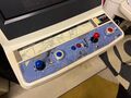 TR Repro Spinner and CP setup

Ultimarc


Axunworks

Compatible Games
| Title | Setup |
|---|---|
| Arkanoid | Left and Right bind to L/R on the harness |
| Arkanoid - Revenge of DOH | Left and Right bind to L/R on the harness |
| Arkanoid Returns | Left and Right bind to L/R on the harness |
| Block Block | Connectors on official Capcom JAMMA adapter |
| Cameltry | Left and Right bind to L/R on the harness |
| Eco Fighters | Connectors on official Capcom JAMMA adapter |
| Forgotten Worlds | Onboard PCB connector |
| Puzz Loop | CN6 pinout 1. +5VDC 2. 1p 3. 2p 4. - 5. - 6. 1p 7. 2p 8. GND [2] |
| Puzz Loop 2 | Connectors on official Capcom JAMMA adapter |
- External list of compatible games(includes alternative 2 way games such as Puzzle Bobble)
Pinouts
Seimitsu LS-29
Pin1: X1
Pin2: +5 Volts
Pin3: GND
Pin4: X2[3]
Taito 4 Pin

Pin1: Right
Pin2: +5 Volts
Pin3: GND
Pin4: Left[4]
Taito 6 Pin

Pin1: +5 Volts
Pin2: +5 Volts
Pin3: GND
Pin4: GND
Pin5: Left
Pin6: Right[5]
Capcom

Pin1: B
Pin2: +5 Volts
Pin3: GND
Pin4: A
Ultimarc to USB Interface

Pin1: +5 Volts (Brown)
Pin2: X2 (Green)
Pin3: GND (White)
Pin4: X1 (Yellow)
Pin5: Empty[6]
MikesArcade repro

Pin1: X1
Pin2: +5 Volts
Pin3: GND
Pin4: X2[7]