Spinner: Difference between revisions
Wigsplitta (talk | contribs) No edit summary |
Wigsplitta (talk | contribs) No edit summary |
||
| Line 40: | Line 40: | ||
Image:Ultimarc_Spinner_2.jpg | Image:Ultimarc_Spinner_2.jpg | ||
Image:Ultimarc_Spinner_3.jpg | Image:Ultimarc_Spinner_3.jpg | ||
Image: Ultimarc_Spinner_USB.jpg | Image:Ultimarc_Spinner_USB.jpg | ||
</gallery> | </gallery> | ||
| Line 74: | Line 74: | ||
Pin1: +5 Volts, Pin2: +5 Volts, Pin3: GND, Pin4: GND, Pin5: Left, Pin6: Right<ref>[https://forums.arcade-museum.com/threads/taito-spinner-6-pin-wiring.494679 KLOV forums]</ref> | Pin1: +5 Volts, Pin2: +5 Volts, Pin3: GND, Pin4: GND, Pin5: Left, Pin6: Right<ref>[https://forums.arcade-museum.com/threads/taito-spinner-6-pin-wiring.494679 KLOV forums]</ref> | ||
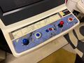
== Ultimarc to USB adaptor Pinout == | == Ultimarc to USB adaptor Pinout ==<ref>[https://www.ultimarc.com/trackballs-and-spinners/spinners/spintrak Ultimarc]</ref> | ||
Pin1: +5 Volts (Brown) | [[File:Ultimarc_Spinner_USB.jpg|150px|thumb|right]] | ||
Pin1: +5 Volts (Brown) | |||
Pin2: X2 (Green) | |||
Pin3: GND (White) | |||
Pin4: X1 (Yellow) | |||
Pin5 Empty | |||
Revision as of 19:51, 22 May 2024
A Spinner is a type of control interface used in several arcade titles. To install a spinner, depending on the type, you either need to remove the knob and install it like a joystick, or completely disassemble the spinner and remove the c-ring to release the shaft, and then re-build the spinner around the control panel. When installing the spinner, make sure the encoder wheel doesn't touch the optical switches when in upright position, as this will cause resistance on the wheel and make the spinner difficult to use.
Gallery
Taito
-
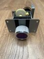 Purple 4 gear flat plate
 -
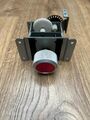 Red 4 gear 'S' plate
 -
-


-
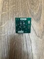 4 pin Opto pcb
 -
 4 pin Opto pcb
 -
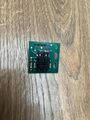
 6 pin Opto pcb
 -
 6 pin Opto pcb


-
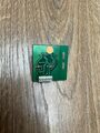
 Wico Opto pcb
 -
 Wico Opto pcb
 -
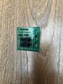
 Repro Opto pcb
 -
 Repro Opto pcb


Capcom
-
 Repro Spinner and CP setup

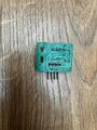
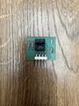
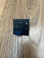
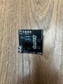
Ultimarc


Compatible Games
| Title | Setup |
|---|---|
| Arkanoid | Left and Right bind to L/R on the harness |
| Arkanoid - Revenge of DOH | Left and Right bind to L/R on the harness |
| Arkanoid Returns | Left and Right bind to L/R on the harness |
| Block Block | Connectors on official Capcom JAMMA adapter |
| Cameltry | Left and Right bind to L/R on the harness |
| Puzz Loop | CN6 pinout 1. +5VDC 2. 1p 3. 2p 4. - 5. - 6. 1p 7. 2p 8. GND [1] |
| Puzz Loop 2 | Connectors on official Capcom JAMMA adapter |
Seimitsu LS-29 Pinout
Pin1: X1, Pin2: +5 Volts, Pin3: GND, Pin4: X2[2]
Taito 4 Pin Pinout
Pin1: Right, Pin2: +5 Volts, Pin3: GND, Pin4: Left[3]
Taito 6 Pin Pinout
Pin1: +5 Volts, Pin2: +5 Volts, Pin3: GND, Pin4: GND, Pin5: Left, Pin6: Right[4]
== Ultimarc to USB adaptor Pinout ==[5]

Pin1: +5 Volts (Brown) Pin2: X2 (Green) Pin3: GND (White) Pin4: X1 (Yellow) Pin5 Empty