Sega Blast City Wiring Guide
Control panel
The pinout is identical to the naomi pinout expect for the 10 pin AMP UP connector.

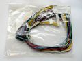
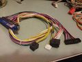
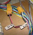
Using the official Sega extra button loom ( 600-6227-10 ), this is how you wire a kick harness to the cab io's CN8 .
| CN8 ( JST NH ) | function | CPS1 ( JST NH ) | CPS2 ( HRS DF1B ) |
|---|---|---|---|
| 1 | P1 light kick | 3 | 19 |
| 2 | P2 light kick | 7 | 21 |
| 3 | P1 medium kick | 4 | 17 |
| 4 | P2 medium kick | 8 | 23 |
| 5 | P1 strong kick | 5 | 15 |
| 6 | P2 strong kick | 9 | 9 |
| 7 | GND | 1 | 34 |
| 8 | GND | 2 | 35 |
Cabinet I/O Board
This Passive PCB ( Sega part # 839-0894 ) links almost all inputs and outputs together and is a big part of why the Blast City is so versatile.

| CONNECTOR | FUNCTION | SPEC | PINOUT | ||||||||||||||||||||||||||||||||||||||||||||
|---|---|---|---|---|---|---|---|---|---|---|---|---|---|---|---|---|---|---|---|---|---|---|---|---|---|---|---|---|---|---|---|---|---|---|---|---|---|---|---|---|---|---|---|---|---|---|---|
| CN1 | DC Power INPUT (From PSU 400-5325) | Molex MLX |
| ||||||||||||||||||||||||||||||||||||||||||||
| CN2 | AC Power INPUT (From Door Switch) & OUTPUT | Molex MLX |
| ||||||||||||||||||||||||||||||||||||||||||||
| CN3 | DC Power OUTPUT | AMP UP |
| ||||||||||||||||||||||||||||||||||||||||||||
| CN4 | JAMMA Coin Meter (Pin:8、J) & Coin Chute (Pin:16、T) INPUT | JST NH |
| ||||||||||||||||||||||||||||||||||||||||||||
| CN5 | JAMMA / JVS / Model3 I/O
|
JST RA |
| ||||||||||||||||||||||||||||||||||||||||||||
| CN6 | General I/O (From game board or I/O board)Note7&8
|
JST NH |
| ||||||||||||||||||||||||||||||||||||||||||||
| CN7 | vs kit | JST RA | |||||||||||||||||||||||||||||||||||||||||||||
| CN8 | to 10pin amp in panel | JST NH | |||||||||||||||||||||||||||||||||||||||||||||
| CN9 | to coin meter / coin swith | JST VH | |||||||||||||||||||||||||||||||||||||||||||||
| CN10 | to cabinet output harness | JST RA | |||||||||||||||||||||||||||||||||||||||||||||
| CN11 | General I/O (Default connect to billboard connector) | JST NH | |||||||||||||||||||||||||||||||||||||||||||||
| (CN12) | JAMMA Coin Chute 1 (Pin:16) OUTPUT | JST NH |
| ||||||||||||||||||||||||||||||||||||||||||||
| (CN13) | AC Power OUTPUT | AMP UP |
|
Model3 Wiring
The 600-6738-20 loom handles i/o and audio/video. you can also use the DB15 connector with regular VGA cable if your monitor has an DB15 input. Note that it is not VGA signal, although the pinout is the same, the model3 outputs in 24khz.
600-6738-20

JAMMA Conversion
The 600-6738-21 loom is designed for jamma only. The 600-7143-001 ( see below ) loom can also be used ( set the inline audio selector to "speaker" ).
- -5v is not supplied.
- disconnect the VGA source ( even if powered off ) if using a JAMMA video source, else the monitor will not properly detect voltage levels. This will cause the screen to be quite dim.
600-6738-21

JVS Conversion
The Blast City is "JVS ready". This means that by itself it cannot handle the JVS serial protocol, but it can handle VGA inputs, Stereo/RCA inputs and provide JVS power plugs.
You will need the following to use JVS systems in your Blast City:
- Jamma/JVS loom ( 600-7143-001 , aka 001 loom )
- sega or capcom JAMMA i/o adapter
Optional:
- kick loom ( see CN8 pinout above )
- analog loom ( 600-7143-004 , sega i/o only )
- JVS Power Supply ( if running naomi+GD-ROM attachment, chihiro or newer systems )
The sega JAMMA io adapter does not convert video signals, therefore you can run 15k or 31k through the jamma i/o board's VGA input if you wish. The signal will just go through the cabinet io.

600-7143-001
600-7143-001 audio selector


Manual
Power Wiring
The kill switch closed by the service door can easily be disconnected and replaced by a homemade loop cable. all you need a 4pin AMP UP male connector.

