Twin Cobra Repair Logs
Repairer: Asayuki
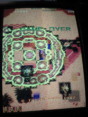
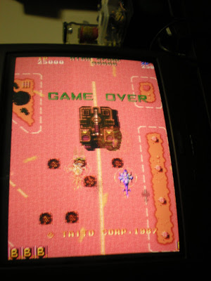
Symptom: Random tearing and shifting of the background and text layer; foreground layer and sprites are fine.
Strikingly similar to the original, as usual with bootlegs the layout has been modified to accomodate the extra circuitry replacing custom chips. Specifically the T.T-1 have been replaced with glue logic on board and the T.TC-4 (TMS320 DSP used for protection) has been replaced with an off-the-shelf part and its internal ROM contents have been brought outside into some EPROMs. The replacement of T.T-2 chips has required an additional board due to space constraints.
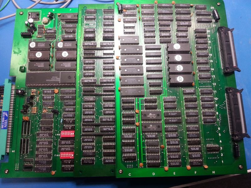
The game showed tearing and shifting of the background layer and of the text layer, while the foreground layer and sprites were fine. The audio is good, and the game is playable.

After triggering the scope on the vertical sync, the investigation started. Poking around with the scope showed immediately that the group of EPROMs located on the center of the board hosted the graphic data for the text layer, the background layer and the foreground layer. The addressing of the EPROMs looked regular on the top part of the screen, but at a certain variable raster line it got messed up until the next vertical sync. Looking around further highlighted a very interesting signal which stayed silent most of the time and then made some pulses right when the timing got messed up. Following the signal through several decoding logics brought to the 68000. Using this signal as a qualifier and looking at the address bus bit by bit showed that this signal is the write pulse indicating that the CPU is accessing the registers inside the T.T-2 customs (as confirmed by MAME's source code stating the address).
This pulse comes to pin 20 of the T.T-2 closest to the Z80 (text layer address generator), and is jumping all over the place. The other two T.T-2 (for background and foreground), being identical to the other one, also have a write pulse at pin 20 which is however much more stable in place around the vertical blanking. This made me think the CPU might be writing at the wrong moment to those registers and thereby causing the issue, maybe because it was stuck somewhere waiting. This has been a wrong assumption that brought me completely off-track and has been quite difficult to disprove. I ended up dumping the program ROMs, investigating and dumping the protection DSP EPROMs and even replacing the 68000 until I reluctantly accepted that the write pulse in question was not the issue although the scope was hinting otherwise.
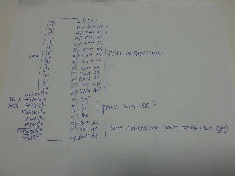
Apart from the MAME source there is not much info around on this board, therefore delving into the logic was the only way out. Completely reverse-engineering the board replacing the three T.T-2 chips was the next step, because all the signals directed to the ROMs and RAMs were coming from there. First of all the pins of the custom T.T-2 were traced to RAMs and ROMs; extracting the netlist allowed me to determine the pinout of the T.T-2 which you can see below.
The result of the reverse-engineering effort is the image shown below; this is what really could be inside the T.T-2, or actually it's the way these bootleggers reproduced its functionality.
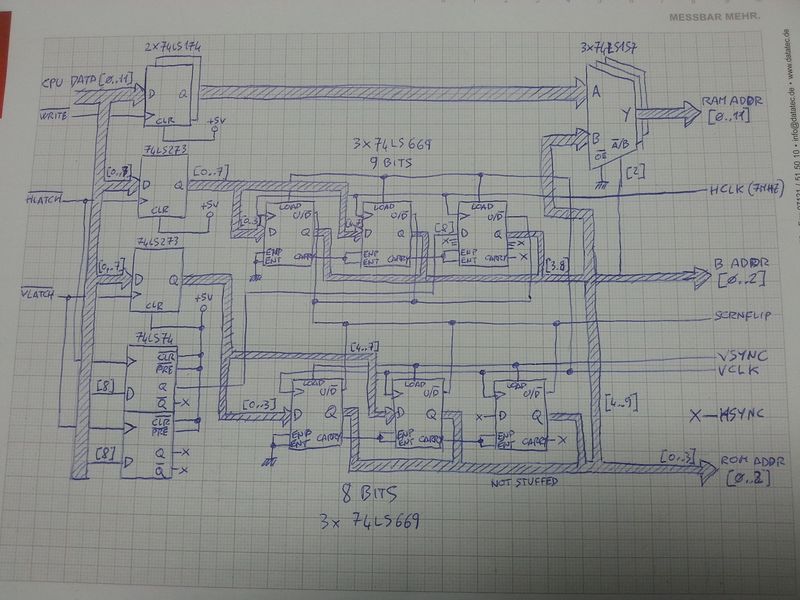
This schematic makes a lot of sense actually. The T.T-2 receives sync, clock and timing information as well as the data bus of the CPU, presents the CPU with registers that can be written to control the scrolling of each layer separately and finally provides pins at the output which drive the address busses of the tilemap RAMs. The data read from the tilemap RAM is then used to address the ROMs which finally provide the graphic data for rendering. The CPU is however also able to drive the outputs of the T.T-2 directly in order to write new tilemap data to the RAM. The T.T-2 has two internal counters for horizontal and vertical scanning, and also has a pin allowing backwards counting and thereby screen flipping.
All registers inside the T.T-2 contain 8 or 9 bit values that can be programmed at any time, because the values in those registers are only loaded into the counters during the vertical blank through a pulse issued by the hardware. Since all inputs to the T.T-2 look stable and coherent except for WRITE# at pin 20, this means the defect is on the board that emulates those T.T-2 chips.
Once the above schematic was available, it was very easy to pinpoint one chip responsible for the issue: one of the 74LS669 counters. This bidirectional loadable counter is fed HSYNC as a clock pulse and reloaded every VSYNC, basically showing a new value at the output with every line and thereby addressing a new row of pixels for the selected tile. The WRITE# pulse does not even reach it, however the traces involved with the operation of the WRITE# pulse run in the proximity of the clock pulse for this counter. Add to it that this board has absolutely no decoupling capacitor and you get the perfect recipe for troubles. Result: the writes of the CPU to the T.T-2 registers couple capacitively to the HSYNC line used as a clock. Ground bounce amplifies the issue and this makes glitches of significant amplitude appear on the latter signal, high enough to induce the counter in advancing one step. It was quite difficult to catch this on the scope, but this demonstrated how the poor (probably automated) routing of this bootleg add-on card actually is the culprit of the problem. To confirm this theory, I have replaced the 74LS669 and also the 74LS175 driving the sync signals at their origin; all to no avail.
As an added information, by the way, the sync signals on this board are generated by the very famous 6845/6545 CRTC controller. Although it has memory refresh and character display addressing functionalities, it has been used because it generates the HSYNC, VSYNC and BLANK signals through a programmable interface. These get then synchronized to the clock domain of the Toaplan design through a 74LS175 quad latch. The funny thing about this is that the 74LS175 finds itself driving a whole lot of logic gates, not only around the Toaplan board but also on the bootleg card replacing the Toaplan customs. I wonder how can the sync signals manage to look so wide in amplitude and so smoothly rising and falling...
I have finally solved the issue by adding a total of 200pF distributed capacitance at the clock input pins of those counters as it can be seen on the photo below. As one of the counters was more problematic than the others, I have also added a 100nF supply decoupling capacitor for good measure.

This mitigates the glitches enough to make them invisible to the clocking circuitry of the counters. This really is a hack, yes; however a proper solution would have required rerouting the entire card and adding all needed 100nF capacitors...
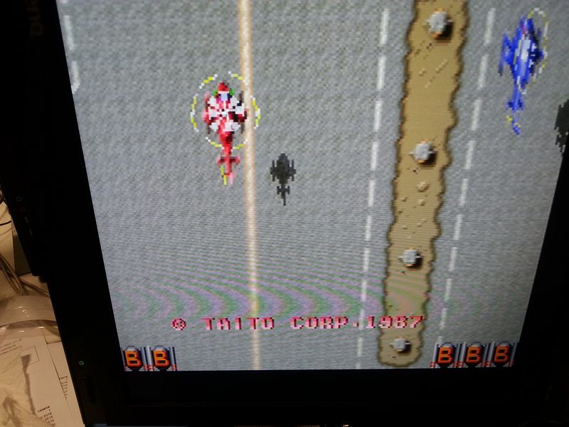
The game now shows a rock-solid picture, as also confirmed by the quite long playing session this awesome shmup deserved ever since the start of this repair. ;)


Repairer: Apocalypse
Source: Twin Cobra - Taito 1987 (repair log)
Game was completely dead: black screen, no sound.
On this hardware many things can lead to this as it seems the self test requires a lot of things to be operational before displaying the RAM/ROM test screen.
1) Getting the board to boot
I started to probe the board and found many signals were absent on the top board. In fact they were present only a fraction of second on start-up. Long story short they were coming from various LS245s, themselves having their enable pin (/E signal) coming directly from address line A16 of the main CPU (68k). I was a bit lost so went back to the basics : RAMs.
One of them on the top board had all its data pins stuck high. I took the chance to piggyback it and game booted:
But with no sprites at all...
2) Fixing the graphic glitches
The concerned cicuitry is on the top board and probing the six 2148 RAMs I found one had data signals tied low. They were coming from a LS244 which in turn had inputs stuck low. This lead me to a LS74 and finally to a series of LS166 which had their shift/load pins shorted to Vcc.
Due to the corrosion of the board I wasn't able to determine the point of least resistance so I pulled the chips I identified were connected to this stuck signal:
- LS166 @ 13E pin 15
- LS166 @ 14E pin 15
- LS166 @ 16E pin 15
- LS166 @ 17E pin 15
- LS374 @ 23D pin 11
The last chip I pulled was the LS166 @ 13E and it was indeed the culprit.
Unfortunately I didn't have any in stock but I powered the board without it in hope for any improvement : sprites were back. Corrupted but back:
After I received the replacement part I put it back on the board and:
Game fixed.


