Gyruss Repair Logs
Repairer: cal2
Forum Thread: Gyruss PCB Repair
I bought a pcb lot in which there was a konami pcb. I dumped some eproms and they matched the gyruss romset.
The board was very corroded and would not boot at all. The edge connector was so corroded that the board wasn't powered at all.
By cleaning the edge connector, the game booted almost flawlessly. Everything was good except for sound and sprites. The text layer and colors however were good.
I found at least three eproms that didn't matched the gyruss rom set. First was GY11 on the sound board simply because one pin broke when I removed it from the board, because of corrosion.
The konami-1 sub cpu code eprom was almost completly eaten by corrosion so it wasn't a surprise it matched no set.
Also, an other graphic rom was bad.
I replaced all eproms (2764) by 27512 by duplicating the rom content.
I powered the board again and tada, sprites were all there and working. However, after powering off and on the board again, the sprites were gone again
So, I first removed all chips from the corroded part of the main pcb, and cleaned it using vinegar and alcool. Then I put sockets and new replacement chips.
Still no sprites, but the pcb was looking a lot cleaner
I put a new socket for the konami1 cpu code eprom since it was corroded also.
Still nothing. I desoldered the shared ram between the z80 and konami1 cpu which tested ok.
However the data bus on the shared ram wasn't nice looking. So I desoldered and tested the two 74LS245 related to it. One was buggy. Replaced it.
Still nothing
According to the scope, sometimes the konami1 cpu was running, and sometimes not. As if it was crashing.
The konami1 cpu is a custom 6809 which scrambles some lines on opcodes only. Since I had no other board that uses it, I couldn't replace it to test if it was ok.
I assumed it was ok, but crashing due to various bus issues.
To be sure, I replaced and socketed the two 74LS244 on the konami1 address bus.
Still nothing.
Then using the scope, I noticed that one pin of the 74LS245 on the konami1 data bus was different than the others. Actually, the signal was between 0 and 1/2 VCC, not 0 and VCC.
So I replaced it and got some sprites on screen
However the sprites were flickering and it was obvious that there was a positionning problem for them since they were moving wrong.
Also, the sprites stopped moving after a minute and the konami1 was dead again as if it had crashed.
Looking at the gyruss mame source code, I found that the konami1 cpu had work ram, sprite ram, shared ram between it and the main z80 and of course rom code.
I knew where the sprite ram, shared ram and rom code were on the pcb, but couldn't find the work ram location.
I first thought that the custom konami1 cpu had internal ram. But looking at other konami games using it, it was obvious it hadn't since the ram memory range was often different than in gyruss.
Then, looking at the 4x 4bit sprite ram chips, I found that the total was exactly the same as the total of the konami1 work ram and sprite ram.
In fact, konami uses the sprite ram as work ram for the konami 1 cpu.
This means that program variables and stack are stored in the sprite ram.
Bad ram would explain why the konami1 cpu kept crashing.
I desoldered the 4x 4bit srams and found that two of them had bad pins.
Replacing the sram with compatible chips (5114), fixed the sprites problem.
Now sprites are good and the konami1 cpu doesn't crash anymore
Next steps:
- fix the inputs for this game since some inputs are stuck high.
- fix the sound
Repair Logs converted to wiki format by Brad from Aussie Arcade.
Repairer: Asayuki
Symptom: Audio issues
Some months ago I received some boards, among which two Gyruss ones. One of them was marked as broken; the other one was deemed working but with audio issues. A quick look identified them both immediately as bootlegs. The reason why I like working on bootlegs is that, although you don't get the board to exactly match the schematics (if at all available), you get standard off-the-shelf components to replace all those pesky custom chips which may make you waste several hours of failure hunting just to find out that the issue is inside one of those irreplaceable parts. With enough will, and access to obsolete parts, you have a good chance to fix whatever issue there might be; and this repair is a perfect example of that.
The two board sets were identical, and the top board visually matched the original audio board perfectly; a good sign that the PCB I was looking into likely matched the official schematics. With regard to the video board however, only the general placement of the functional blocks was matching the original; there were a lot more components on my boards in order to compensate for the missing customs. MAME says that the Gyruss set has a Z80 and an 8039 on the audio board, plus a Z80 and a “Konami 1” CPU on the video board. The Konami 1 is nothing more than a 6809 with internal decryption of the sole opcodes, as confirmed by MAME; and of course my board has an off-the-shelf 6809 with lots of logic around it. Either the added logic has been a much cheaper solution to the bootleggers or they got leaked an early design board they could just copy. The broken board set was missing two big PALs in that area, but at least it was a matching board set full of spare parts.
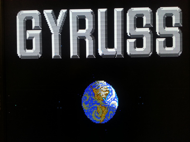
Plugging in the working board set required a Konami Classic adapter, which I wired up quickly enough. Powering up the board immediately produced a good video signal with a working attract mode, but with a confused audio. Well, ok; at least that matches what the seller has declared. The board has been designed with five (!) AY-3-8910 sound generators plus an 8039 dedicated to sample playback for a total of 16 voices polyphony. And that's not all. Two of those generators have raw tunable low-pass filters and the entire group is arranged as three generators on one power amplifier and two generators plus sample playback on another; this even means stereo sound if your cabinet has two speakers. WOW! That's why I remember the tune from this game to be so cool. Thanks to the available schematics, it has been very easy to understand the audio board: the sample player revolves around the 8039 and its EPROM, and is controlled by the Z80 via a latch. Playback occurs through the classic resistor-based DAC. The Z80 also accesses two EPROMs, two 2114 RAMs (1k by 4bits) and a latch allowing unidirectional instructions from the video board. Firing up the scope and poking around immediately identified the reason of the issue: address lines were fine, but the data lines were all disturbed and low in amplitude. No wonder the audio was having issues and indeed crashing after a while... At a closer look half of the data bus was showing a different degradation than the other half. The two 2114 RAM chips were of course the suspect number one. Ordering some replacements over eBay and plugging them into the board restored the awesomeness of this game's audio track, along with all its sound effects. Very easy one. Unfortunately, letting the game play for a while made two other “hidden” issues surface: first of all the title logo had a funny green where a dark grey was supposed to be; second, the sprites had more and more colour glitches with time. Oh no... not again!

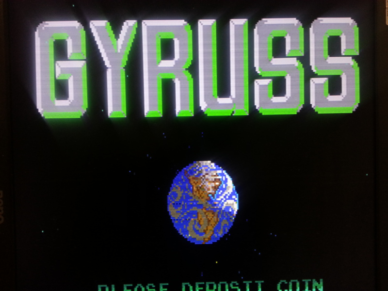
The picture only shows a few glitches on the Earth graphics, but this was an unlucky shot: it is much worse than that.
Next step: dump of all the EPROMs, which just confirmed that the board was running the official protected Konami romset. So, the EPROMs were fine. The schematics of the video part are unfortunately full of custom unlabelled stuff which greatly diminishes their usefulness. While poking around with the scope I realized that the board actually has no other tilemap layer than the non scrolling text page. Both the starfield and a part of the Earth as displayed on the title logo are made of sprites.
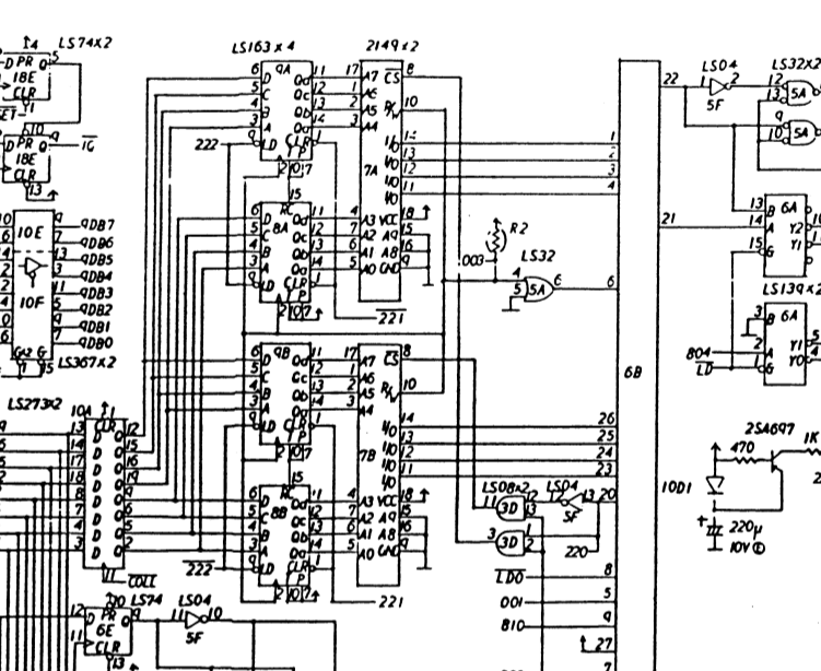
With regard to the video board schematics, the top part of it handles the sprites themselves, while the bottom part handles the text layer which also generates the Gyruss logo as tiles. The Z80 boss sits at the top left of the schematics and its code is stored in the EPROMs labelled 1, 2 and 3 for a total of 24kB. The 6809 is the custom located at 18F which reads a 2764 EPROM located at 19E. There are further 4 EPROMs around, containing the sprite graphics and another 2764 for the tilemap data of the text screen; a total of 9 non-volatile memories plus a lot of RAM all over the place. Let's start with the colour glitches on the sprites. Fortunately for me, the defect proved to be temperature-dependent. This made it easy to isolate, thanks to the good old freezer-spray. I had no useful result until I happened to freeze one of the two Intel QD2149 RAMs labelled into the schematics as 7A and 7B. This completely restored the glitchy sprites. Aha!

A quick scoping at them showed unhealthy data lines. I desoldered the two 6148 that were mounted on the other Gyruss board in the same position and dropped them into the sockets. The issue got even worse: sprites were there but mixed to some ugly red lines, and the data bus was still ill. Obviously those RAMs were even more broken. I ordered replacement parts and, to my big surprise, the original defect persisted. Obviously there was another responsible for this fault; that is another IC which was trying an arm race with the RAMs to impose a logic level on the bus. The RAMs are driven by a group of four LS163 which generate incrementing addresses based on a starting value imposed by something else through a latch, and this runs continuously with clock and read/write pulses generated in hardware. It could be that it's a double line buffer for pixel data. The data bus of the RAMs is only connected to the custom chip at 6B therefore, if this was an original board, I had just wasted my time because those RAMs are written by none other than this Konami custom. The schematics were now all of a sudden useless and I had to venture into the PCB to trace back from the RAMs to some kind of three-state capable IC that allowed the RAMs to be written. I found out that those RAMs are connected to a dual quad-input AND gate which is used to check when the data bus has a 1111 combination (most likely for transparency). They are also connected to the D side of an octal latch which is supposed to fetch data from them. Finally, they run to an LS244 nearby which allows some other logic to write to them. I honestly wouldn't be surprised to see the decapped custom contain exactly this stuff. Removing the LS244 chip made the bus gain back its 5V amplitude, and replacing it has sorted out the problem; now the board can stay on for several hours without showing glitches anymore.

On to the next defect: the funny green colour on the logo. The bottom right side of the schematics has three PALs, two of which (at 3E and 6F) provide colour indexes out of the data from both the sprite layer and the text layer, acting as look-up tables. The PAL at 6F is dedicated to the sprite layer. It gets fed with 8 inputs, 4 of which determine which one of 16 palettes to use; the other 4 bits determine which colour to look-up in the selected palette. The PAL at 3E is dedicated to the text layer instead. It gets fed with 6 inputs, 2 of which determine which one of 4 palettes to use; the other 4 bits determine which colour to look-up in the selected palette. This explains why MAME uses a palette of 320 colours (16+4=20 palettes by 16 colours each).

The pesky custom I have been dealing with does not only handle the video RAM; it also reads the sprite pixel colour index from the PAL at 6F, adds a 5th bit to it and does priority encoding for the two layers. As a result, the MUX at 4A is ordered to take the colour index coming from the text layer PAL at 3E or the 5bit index coming from the custom chip itself. This information is then latched and fed to the third PAL at 2A which finally generates an 8bit RGB323 word to feed to the resistor-based video DAC. Since the PAL at 2A only has five inputs, it means that Gyruss works with a total of 32 colours. The 20 palettes are nothing more than 20 different selections out of those 32 global colours. As the funny green is the only colour defect that can be seen around, either the MUX at 4A, the PAL at 3E or the PAL at 2A are to blame. The latter proved to be defective when replaced with the one donated from the other set. Luckily, both were already socketed. I am pretty happy to have been able to add this masterpiece to my collection. Yay for shmups!


