Basic Diagnostics
Even if you're not prepared to go into depth repairing game boards there are a few checks that every home arcade owner should perform on any presumed faulty PCBs before discarding them or asking for greater assistance or repair services.
Checking Voltages
If you suspect something is wrong with your PSU or the game doesn't turn on or turns on without sound, the first thing you should do is to power off the cabinet and remove the PCB. The last thing you want to do is subject the PCB to even more damage. Once the PCB is removed, get a multimeter and measure at least the +5v. You should also check the -5v and +12v since you're already there. The voltages should measure exactly when a PCB is plugged in, unless you know for certain that a particular PCB requires an unusual voltage (such as Mortal Kombat boards needing between -5.15v to -5.2v for sound to work). Get your voltages to a safe level first without a PCB then turn the cabinet off, plug the PCB you want back into the machine and test the voltages again, making your final adjustments. Sega Blast City owners should see the linked page for even more basic diagnostics, to be performed prior to any of these steps.
Checking for broken traces
Often over the years boards get small scratches to them. If this scratch runs through a trace on the board, it will break the circuit and cause the game to malfunction. Almost any issue can be caused by a broken trace. Using a magnifying glass and in bright light, check the board thoroughly for broken traces. Any suspect traces can be checked using a multimeter set to continuity mode, with a probe on each end of the trace. Continuity implies the trace is fine, while no continuity implies the trace is damaged and needs to be patched. A proper check of a board can take up to an hour depending on the complexity of the PCB.
Reseating Cables and EPROMs
As the years pass, oxide builds up on socketed components such as EPROM's and cables causing them to no longer connect properly with their sockets. Reseating these breaks down the oxide, creating a better connection. If the issues persist, and the PCB uses multiple of the same ribbon cables, try swapping the cables - if the fault changes, the cable may be the issue.
Identifying and Repairing Dry Joints

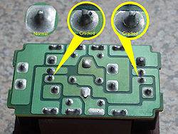
If too little solder is applied to a solder joint, it can dry out, breaking down the connection. These can be visually identified with inspection under good lighting, and tested using a multimeter - follow the trace to see where the connection goes, set the multimeter to the continuity test, and place a probe on the leg of each component. If the multimeter does not beep, the solder joint will need to be reflowed with a soldering iron, adding additional solder to ensure a strong bond. Please note that even if the continuity test is successful, the solder joint may still cause issues - with a little flex in the board, the solder may no longer connect and cause issues to appear. It's best to reflow any identified dry solder joints for future-proofing.
Further Investigation
Has the issue persisted? take a look at our Game Board Repair Guide for further advice.