Psychic 5 Repair Logs
Repairer: channelmaniac
Symtpom: Dead. Power supply fluctuates and/or shuts down.
Checked board for shorts. Could not find any. Checked the 5v line to the 2nd board and found it went to ground. Flipped the 2nd board over for proper orientation and tested game.
The way the connectors are wired if the board is plugged in backwards it will swap +5v and ground wires. The only thing that saved this board from damage was that it was plugged into switching power supplies that had automatically shut down.
Symptom: Background graphics are corrupt.
Replaced a bad 6264 SRAM IC on the video board and tested.
Repairer: Asayuki
Symptom: The board is dead.
This repair features a colleague of mine who goes by the name of Jorge. This was his first contact with arcade boards, and he loved this joint effort ...although he ended up clearly stating that some time will have to pass until he comes around again to ask what funny things I'm doing after my shift with obsolete-looking hardware. Thanks pal! Your help has been precious!
I bought this board as part of a stash from an ex operator, and since it's a bootleg there was no indication whatsoever about what game it was. A mistery board! The silkscreen was as poor as it could be, but at least it stated the part numbers of the single ICs instead of just the designators IC1, IC2, etc. There were no standoffs separating the two boards, just a sheet of carton, and one of the two was completely covered with crud. Scratches were randomly present here and there, some of which even very deep but fortunately not involving traces. This one must have suffered real pain and abuse! The solder joints looked really cheap, but testified that no repair attempt had been carried out on it, which was kind of reliving.
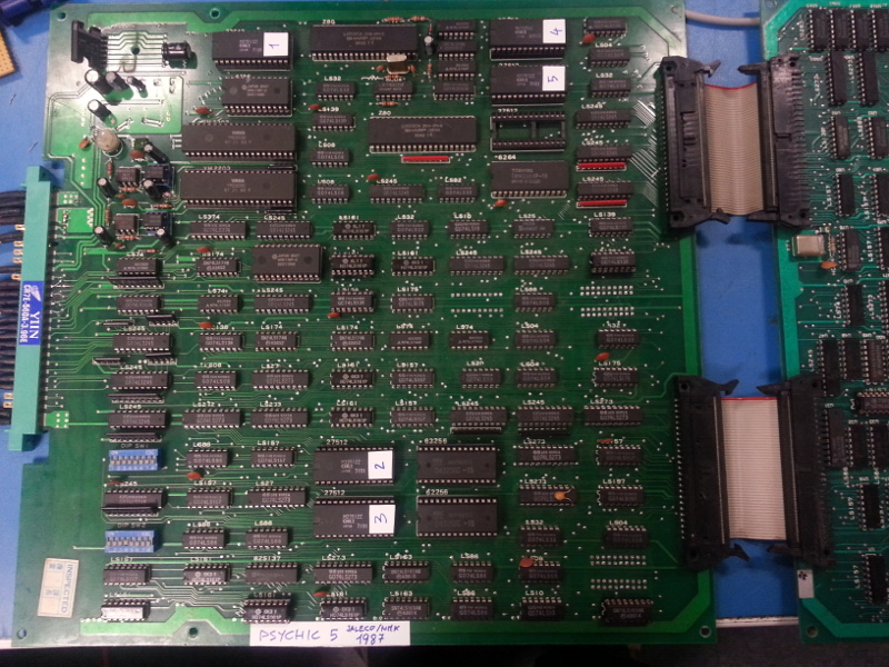
The label with the name which you can see on the board was of course added by me.

The edge connector had ground, +5V and +12V in the right places as well as the speaker pins and the key hole, therefore it certainly was Jamma or close to it. Plugging the board in my woody produced a very jaggy faint blue screen with hissing sounds coming from the horizontal transformer of the monitor. Ok, immediate power off; I rushed a bit too much. It was clearly a dead one.
The board ended up on the surgery desk with just power and speaker connected. A first closer look revealed 2x YM2203, 2xZ80, a lot of RAMs, 5 mask ROMs and 3 EPROMs. All the rest appeared to be standard TTL logic except two well hidden PALs. There were also two crystals for 5 and 12 MHz. The color of the solder mask differed from one board to the other, as well as the retention tabs of the board-to-board IDC connectors, which unfortunately meant that they were originally not coupled together and therefore were probably both broken in some way. This later turned out to be correct: someone had salvaged a good video board from here to fix another set and I ended up with two broken halves. Also, there was an empty socket near one of the mask ROMs which could have indicated that someone salvaged a chip from there. Oh, and... missing heat sink? Or maybe not. Whatever. My hopes to fix this mistery board or even get to know what it was were rapidly decreasing.
Applying power produced a steady AC buzz indicating an unconnected ground somewhere in the audio path, but that was obviously not the priority. First things first: the clocks. 5MHz and 6MHz at the CPUs were good in amplitude and stable in frequency. Both RESETs were high, and using the scope to relate them to the rise of the power supply proved that they were also healty. Let's look at the video outputs. Red was stuck low. Blue was apparently at 100% brightness during the active video. Green was stuck low. Sync was stuck low. And video ground was of course... high?!? OMG! Errr... Blue again; wait, this actually looks like SYNC. A quick check on Speaker + beeping to ground confirmed that the bootleggers had messed up the ordering of the PCB layers: solder and parts sides were swapped. LOL! However, still no clue about what game that was; which means neither schematics nor any other valuable info.
Fiddling around the CPUs again verified that they were both actually running. While scoping around them, the sound CPU started playing something all of a sudden. It was clearly only one channel of a much more complex melody. Me and my colleague stared at each other in disbelief until that confused melody hit a refrain I was very familiar with: a Psychic 5 board was screaming for help, in a tears-broken voice. Dumping the ROMs was a necessary step at this point, and surprise surprise all of them were good and exactly matching the japanese set. This confirmed that the empty slot was meant to be empty in the first place, but also brought us back to square 1. Needless to say, there are no schematics available over the internet and very little information in repair logs, therefore this looked like a very difficult one.
At this point we realized that there were no vertical pulses in the sync signal and decided to trace that back. Probing and tracing brought to an AND gate which obviously received HSYNC on one input while the other was completely silent. Tracing back the supposedly VSYNC trace lead to some cheaply organized vertical counter revolving around a 74LS161. The inputs were all doing stuff but the outputs were stuck low. I had no 161 on stock, therefore had to lend one from a working Gyruss board. Luckily enough, this turned out to be the culprit of the black screen issue. The board started, and greeted us with the mighty tune from the attract mode in all its loud glory. The board was clearly happy about our cares and attentions.
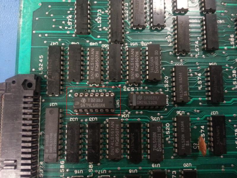
The scope showed that R, G, B and SYNC were good and that the attract mode was really running. Instead of building an adapter, I decided to modify the board by swapping around all needed pins from one layer to the other to make the board really Jamma compatible. Only the coin, start and player controls were left in their original messed-up condition. Time to hook it up to the monitor! Much to our dismay, the repair was still quite incomplete: most sprites, but not all, were missing! Also, the title screen was missing the fast scrolling background previewing the first few levels of the game, and sometimes rebooting the board turned out in a completely silent audio. There was no other choice but to understand how the board worked. *SIGH*
MAME's source code contained a lot of useful info on the board, but they were admittedly incomplete and insufficient due to the missing hardware details on how the logic actually worked. Installing a switch to pull down the BUSREQ pin of the Z80 made it possible to stop the CPU from driving the hardware whenever we wished to do so. This has proven extremely useful in order to determine who was driving what and for what reason.
Below are the results of our reverse-engineering attempt. We have drawn our conclusions by comparing our probing around with and without stopping the CPU, using the information in MAME as a reference. Our conclusions surely are very approximate, but were good enough to investigate further.

In this picture, we have identified the following on the video board:
- RED is the background generator. You can spot the EPROMs containing the 16x16 background tiles and the tilemap RAM. Each tile is actually 4 times 8x8 arranged as a square. This information has come in very handy later on. The RAM is double the size required for the entire tilemap area because the game makes two copies of it: one for the hardware to display the background graphics and the other to use as a collision detection map (probably for walls and destroyable objects you can step onto).
- YELLOW is the foreground generator area. The EPROM contains all the 8x8 tiles that make up the static graphics and the text layer, including the faces of the espers and the EXTRA boxes where the game puts the objects you acquire during your play. The RAM which is in there holds the tilemap of the foreground layer. It is important to notice that the title logo belongs to the foreground graphics. However, we have seen signals on the scope proving that sprites are indeed used during the title screen.
- BLUE is the vertical sync generator.
- GREEN is the palette RAM used for the background and the foreground layers. MAME says that the foreground and background layers have separate palettes but we basically don't believe it because of what we have seen in the hardware.
- CYAN is the palette RAM used for sprites.
- VIOLET is the priority encoder that stacks the graphics layers on top of each other, and also contains the resistor network used as an RGB DAC to output video towards the monitor.
- ORANGE is the horizontal sync generator and the pixel counter from which the entire board is driven. It also contains the 12MHz crystal required to generate the video timings. This clock is divided by 2 and then fed to the CPU as a master clock. The entire game except the audio circuitry uses the timings generated by this area as a time base.

This one instead is the CPU board:
- RED is obviously the audio part, with its CPU, RAM, ROM, audio generators, DACs, mixer and amplifier.
- YELLOW is the main CPU. You can spot there the Z80, the RAM and the three ROM slots, one of which is empty.
- BLUE is the sprite list RAM.
- GREEN is the input buffers and addressing logic used to read dip switches and input lines from the Jamma connector.
- VIOLET is the sprite display logic, with its ROMs and two 32k RAM buffers.
Now, how does all of this work together?
The main CPU issues orders to the audio part through a latch, but the audio has no way of answering back. The CPU can also access the RAMs on the video board (background and foreground tilemaps plus the palettes) to setup the video hardware on which background and foreground to display and in which colors. The pixels generated by those are then prioritized according to the transparent colors and sent out to the DAC. The circuitry is very straightforward: the tilemap gets read by the hardware sequentially, the corresponding data gets read from the ROMs in the right order as specified by the tilemap and forwarded to the priority encoder of the video mixer to compose the image and feed it to the video DAC in real time.
For the sprites, something different happens. Since the game can handle up to 96 sprites, all of which can be mirrored, flipped, chained in a single 32x32 block and have their own palette, creating a circuitry that would do this on the fly line by line would make the board massive. Also considering that all sprites have their own independent coordinates and can be easily stacked one on top of the other if so desired, doing it on the fly is not really convenient. NMK has devised something else there to reduce the costs. The CPU is only allowed to write to the sprite list RAM during a short period in the vertical blanking interval. During the rest of the VBI, the logic frantically reads the sprite list, fetches the data from the ROM accordingly and writes it to a 64k frame buffer dedicated to the sprites. During the active video this buffer is read sequentially and fed to the priority encoder of the video mixer through the ribbon cable connecting to the video board. The frame buffer is one byte per pixel and stores a 4 bit palette number and a 4 bit index into that palette to select a color out of it. The decoding circuitry on the other side of the ribbon cable finally performs the lookup into the palette RAM and generates the 12bit RGB triplets for every pixel in the sprite frame buffer.
As with every frame buffer, the RAM must be cleared before the buffer can be drawn again. NMK used a clever trick to do this: the frame buffer is split into two 8bit chips that take care of odd and even pixels separately. The logic can therefore fetch 16 bits in one cycle and still output them sequentially. This leaves one memory cycle free which is used to write-clear the two bytes that have been just read.
I have personally dedicated one entire evening on verifying each and every single IC in the sprite generator area without results. All ICs seemed to be good but there was no way to assess what was going wrong with the generation of the sprites, and most importantly why some were displayed and some weren't. Given that the sprite logic was working and acting sequentially on the contents of the sprite list RAM, and given the accumulated evidence, the only possible reason why the sprites were not displayed was that the CPU was not commanding the hardware to display them in the first place. However the sprite list RAM was good (as we tried replacing it), the contents of the program ROM were good and the CPU was not crashing or showing any other side effects. The sprites which were on screen displayed flawlessly and according to the demo as shown by MAME, no garbage or glitches whatsoever.
Tracing back from the sprite list RAM to the CPU, qualifying the address lines to the RAM with its write enable pulse was the only way to try and see what was really going on. It turned out that the CPU was addressing only 512 bytes or so per frame, and always the same ones, while the memory is 2048 bytes (1500 or so of which used for the sprites) and never written by anyone else. Very fishy. The circuitry to the right of the sprite list RAM is responsible of allowing this writing window to the main CPU, which seemed too short to enable the CPU to write it entirely. The culprit of the problem proved to be another 74LS161 (4 bit counter with clear and preset) right next to the sprite list RAM that was responsible for timing this window. It was initialized incorrectly due to a micro damage to a trace that slipped through the visual inspection.

Socketing the 161 and repairing the damage finally made Naoki, Akiko and Bunta appear again, along with all their fellas and the background that was not showing up during the title screen. Hurray!
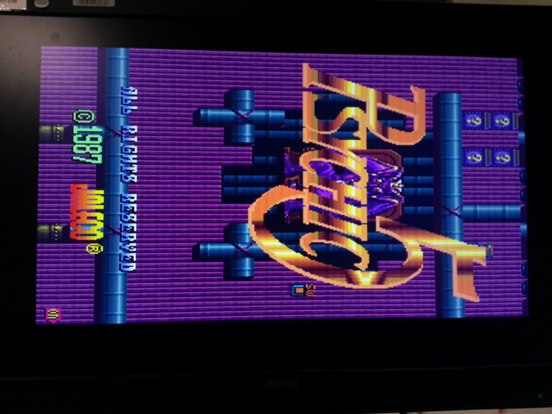
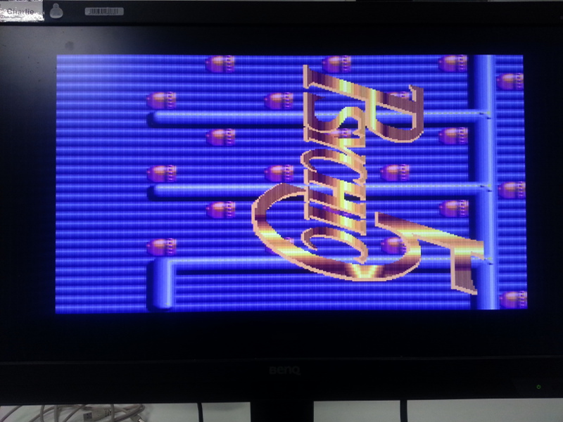
At this point I noticed that the title screen had the background appear blue-ish, while it appeared normally during the game. As MAME does not apply this blue-ish tone to the image, I was fearing another issue. Luckily, this video posted on YouTube by chinitosoccer about an original Jaleco PCB proved that the blue-ish effect was actually intended by NMK and that emulation is never the same thing as the real hardware.
https://www.youtube.com/watch?v=fP2AHmdl-Z4
Unfortunately, closely looking at the fast scrolling background under the title screen highlighted another issue: the top row of background tiles did not make sense with the rest of the level pattern: it obviously was a copy of some other area of the screen but definitely not what was supposed to be there.
This further raised the bar of the technical difficulty for this repair, but at this point nothing on earth could have stopped the rescue of this board; we were getting deeper into the logic.
MAME's info have been useful again. The comments in the source code describe the way in which 8x8 tiles are grouped together to form a 16x16 tile for the background. It also says that the tilemap RAM is organized as 1024x512 pixels, which makes for 64x32 tiles. Each tile is described by two bytes providing the tile ID, the palette ID and the flip flags used by the hardware for rendering. It also says that the screen is encoded bottom-up starting at $C000.
As this is a vertical game, and the screen is therefore rotated by 90 degrees, it means that the top-left cell on our map was at address $C000 and $C001. The one below that was at $C002 and $C003 and so on until the 32th tile, at which point the next column of tiles starts. The first one in there would be at $C040 and $C041 and so on so forth. Now, inspecting the address lines of the tilemap RAM and tracing them back brought (obviously) to the horizontal counter.
Thanks again to the CPU pause hack we have frozen the CPU right when the defect was showing and triggered the scope to a line which had a defective tile in it. Inspecting the horizontal counter in that tiny time frame showed that the counter was fed with the wrong increment value due to bit B3 of the adder having an unxepected state. The counter was good though, because bit B3 was good during the rest of the line. Tracing back that bit ended up showing that it was ultimately driven by an AND gate. One of the inputs of the AND gate was fed with the valid count value while the other was fed with a qualifying pulse that was basically clearing the counter at the end of the active line in preparation for the next. Now, this pulse was evidently coming in too early. One half tile too early to be exact. Result: the last column of tiles was read one byte per tile from the right address and the other byte of each tile was read from somewhere else. No wonder the screen glitches there. Tracing back the qualifying signal brought us to another AND gate. One of the inputs was the qualifying pulse and the other was floating. AHA! Tracing back the floating input brought to a lonely isolated via of the board. WTF?!? It seems that the original board contained a bug which the factory decided to fix with a wire in the production line. Too bad the fix was not applied to this board, as the via was in mint condition. Given the other original-looking fixes on the board, most likely the layout leaked to the bootleggers when the board was still in a prototype stage. Very interesting.
We searched for a pulse on the board that was identical to the one we were seeing on the scope, but delayed a little bit. Feeding it to the dangling AND gate input would have shaped the offending qualifying pulse and ended up knocking some more sense into the horizontal counter logic to address the tilemap RAM correctly.

On the scope the yellow line is HSYNC, while the pink line is the original qualifying pulse. The blue line is the active video blanking signal as fed to the mixer and video DAC logic. We wired this to the lonely gate and bingo! The top line glitch was fixed for good.
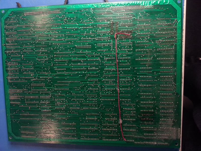
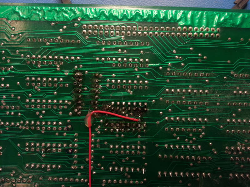
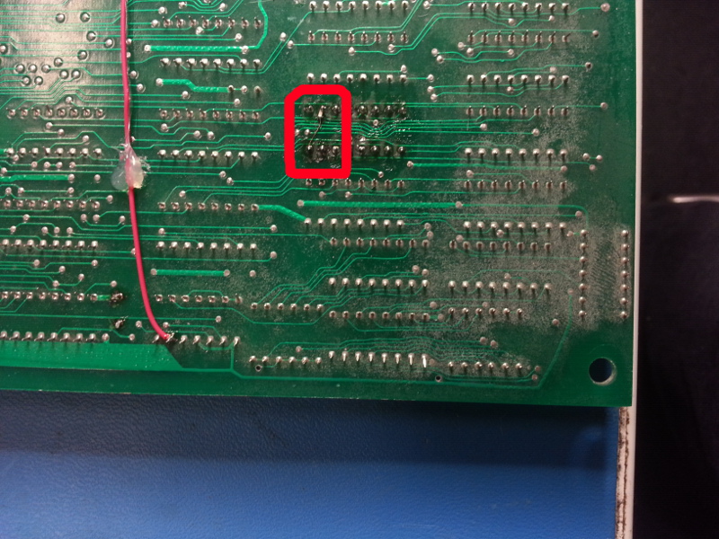
Also marked in red on the above pictures there's the fix for yet another issue: due to the power supply being extremely dirty out of the almost complete lack of 100nF capacitors around the board, the highlighted IC was not identifying the input signals correctly and glitching on pulses with a slow rising edge. This resulted in a randomly wrong bit of the green component on the foreground, making some white pixels of the text randomly glitch to violet. Again, the CPU pause switch has been a precious ally here. Once the scope had been triggered on a known glitching raster line it was just a matter of finding the offending pulse around the mixer area and tracing it back to the offending gate. Replacing the IC proved ineffective, therefore we added a 100nF SMD chip between VCC and GND as close as possible to the power pins, which solved the issue.
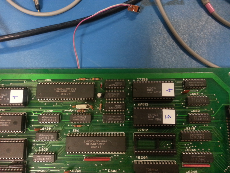
There was one last problem to fix, which kept us wondering all the time due to the fact that it appeared randomly: the audio was still either working completely fine or remaining totally silent when the board booted. Probing the sound CPU when the board booted with no audio showed a completely frozen Z80, but the HALT pin was still high. This pretty much seemed like a bad Z80, but the randomness with which the problem appeared was not convincing. Probing again and again during the repair when the problem appeared finally made a very glitchy out of frequency clock show up. Lightly knocking on the 74HC04 that made the 5MHz crystal oscillate proved the point: the oscillator started behaving funny or stopped, with fatal effects on the playing music. Once the 5MHz crystal and the 74HC04 had been desoldered, a little beeping around made the real issue surface: a tiny fracture of one of the traces near one of the pads of the crystal feedback circuit. Looking closely with the lens and bright light in the back was still baffling our eyes into not seeing the fracture; yet the multimeter doesn't lie. Fixing that trace and soldering back the original components finally ended this lengthy endeavour.
The cheap PCB with all its facepalm issues and cheapo soldering didn't help either: each time the desoldering iron touched the board, the solder mask literally evaporated within a second or two. Although this was a bootleg, I will definitely treasure it; I kind of grown attached to it... IMHO Psychic 5 is one of the best games ever produced by Jaleco, and is always fun and worth playing.

