Sega Mega-Tech Pinout
Jump to navigation
Jump to search
Sega Mega-Tech Pinout.
Overview
-
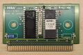
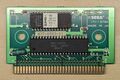
 Mega-Tech PCB
 -
 Parlour Games PCB
 -
 World Championship Soccer PCB


Wiring Harness
Credit to: Kevin Eshbach
Connector CN1 (Lamp)
Use Molex 12 Pin 0.100" Header.
| Pin | Definition |
|---|---|
| 1 | I.1 |
| 2 | I.2 |
| 3 | I.3 |
| 4 | I.4 |
| 5 | N/C |
| 6 | N/C |
| 7 | N/C |
| 8 | N/C |
| 9 | N/C |
| 10 | N/C |
| 11 | N/C |
| 12 | N/C |
Connector CN2 (Select)
Use Molex 25 Pin 0.100" Header.
| Pin | Definition |
|---|---|
| 1 | Select * |
| 2 | N/C |
| 3 | N/C |
| 4 | N/C |
| 5 | Door SW 1 |
| 6 | Door SW 2 |
| 7 | N/C |
| 8 | Test |
| 9 | A.1 |
| 10 | A.2 |
| 11 | A.3 |
| 12 | A.4 |
| 13 | Service |
| 14 | Enter |
| 15 | +5VDC |
| 16 | +5VDC |
| 17 | N/C |
| 18 | Coin Meter |
| 19 | N/C |
| 20 | Ground |
| 21 | Ground |
| 22 | Ground |
| 23 | Ground |
| 24 | Ground |
| 25 | Com A |
Connector CN3 (Sound)
Use Molex 4 Pin 0.100" Header.
| Pin | Definition |
|---|---|
| 1 | Left Speaker (+) |
| 2 | Left Speaker (-) |
| 3 | Right Speaker (+) |
| 4 | Left Speaker (-) |
Connector CN4 (1P)
Use Molex 10 Pin 0.100" Header.
| Pin | Definition |
|---|---|
| 1 | 1P Up* |
| 2 | 1P Down* |
| 3 | 1P Left* |
| 4 | 1P Right* |
| 5 | 1P Shot 1* |
| 6 | 1P Shot 2* |
| 7 | 1P Shot 3* |
| 8 | 1P Start* |
| 9 | Ground |
| 10 | Ground |
- Wired as NO (Normally Open)
Connector CN5 (Gun)
Use Molex 21 Pin 0.100" Header.
Note: Pinout unknown as Sega never released a gun or gun games for this platform.
| Pin | Definition |
|---|---|
| 1 | |
| 2 | |
| 3 | |
| 4 | |
| 6 | |
| 7 | |
| 8 | |
| 9 | |
| 10 | |
| 11 | |
| 12 | |
| 13 | |
| 14 | |
| 15 | |
| 16 | |
| 17 | |
| 18 | |
| 19 | |
| 20 | |
| 21 |
Connector CN6 (Power)
Use Molex 14 Pin 0.100" Header.
| Pin | Definition |
|---|---|
| 1 | +5VDC |
| 2 | +5VDC |
| 3 | +5VDC |
| 4 | +5VDC |
| 6 | N/C |
| 7 | Ground |
| 8 | Ground |
| 9 | Ground |
| 10 | Ground |
| 11 | Ground |
| 12 | N/C |
| 13 | +12VDC |
| 14 | +12VDC |
Connector CN7 (2P)
Use Molex 11 Pin 0.100" Header.
| Pin | Definition |
|---|---|
| 1 | 2P Up* |
| 2 | 2P Down* |
| 3 | 2P Left* |
| 4 | 2P Right* |
| 5 | 2P Shot 1* |
| 6 | 2P Shot 2* |
| 7 | 2P Shot 3* |
| 8 | 2P Start* |
| 9 | Ground |
| 10 | Ground |
- Wired as NO (Normally Open)
Connector CN8 (RGB1) - Main Monitor
Use Molex 6 Pin 0.100" Header.
| Pin | Definition |
|---|---|
| 1 | Video Red (+) |
| 2 | Video Green (+) |
| 3 | Video Blue (+) |
| 4 | Video Sync (-) |
| 5 | Ground |
| 6 | N/C |
Connector CN9 (RGB2) - Secondary Monitor
Use Molex 5 Pin 0.100" Header.
| Pin | Definition |
|---|---|
| 1 | Video Red (+) |
| 2 | Video Green (+) |
| 3 | Video Blue (+) |
| 4 | Video Sync (-) |
| 5 | Ground |
Game Slots
Credit to: Nipedley[1]
| Pin | Function | Pin | Function |
|---|---|---|---|
| A1 | GND | B1 | NC |
| A2 | VCC | B2 | H_RESET |
| A3 | A7 | B3 | NC |
| A4 | A10 | B4 | A8 |
| A5 | A6 | B5 | A9 |
| A6 | A11 | B6 | A17 |
| A7 | A5 | B7 | A18 |
| A8 | A12 | B8 | A19 |
| A9 | A4 | B9 | A20 |
| A10 | A13 | B10 | A21 |
| A11 | A3 | B11 | A22 |
| A12 | A14 | B12 | NC |
| A13 | A2 | B13 | NC |
| A14 | A15 | B14 | /OE (MENU) |
| A15 | A1 | B15 | NC |
| A16 | A16 | B16 | /CAS0 (NC)* |
| A17 | A0 | B17 | /CEO (NC)* |
| A18 | GND | B18 | AS |
| A19 | D7 | B19 | NC |
| A20 | D0 | B20 | DTACK |
| A21 | D8 | B21 | NC |
| A22 | D6 | B22 | D15 |
| A23 | D1 | B23 | D14 |
| A24 | D9 | B24 | D13 |
| A25 | D5 | B25 | D12 |
| A26 | D2 | B26 | /CART |
| A27 | D10 | B27 | /CEO (CE ROM) |
| A28 | D4 | B28 | /LWR |
| A29 | D3 | B29 | /CAS2 |
| A30 | D11 | B30 | /M3 |
| A31 | VCC | B31 | /TIME |
| A32 | GND | B32 | /CAS0 (OE ROM) |
B16 and B17 MT are also /CAS0, /CEO signals but B27 and B32 are the slot-switched /CAS0 and /CEO specific for MT.
The Megatech switches these signals on/off from slot to slot, to enable or disable the specific cart.